Decoding Electrical Schematics: A Comprehensive Guide to Symbols
Ever looked at an electrical schematic and felt overwhelmed by the cryptic symbols scattered across the page? Understanding these symbols is fundamental to working with electrical systems, whether you're a seasoned electrician or a DIY enthusiast. This guide dives deep into the world of electrical schematic symbols, providing a comprehensive understanding of their meaning and importance.
Electrical schematics are the language of electrical circuits. They provide a visual representation of the components and connections within a system, allowing professionals to design, analyze, and troubleshoot electrical circuits effectively. Imagine trying to build a complex electronic device without a blueprint; similarly, working with electricity without understanding schematic symbols is like navigating a city without a map. This article will equip you with the knowledge to confidently interpret these symbols and unlock the secrets within electrical diagrams.
The use of standardized graphical representations for electrical components dates back to the late 19th century with the rise of complex electrical systems. As electricity became more prevalent in homes and industries, the need for a universal language to represent circuit elements became crucial. Early electrical schematic symbols were often simplistic, evolving over time into the standardized representations we recognize today. Organizations like the IEEE (Institute of Electrical and Electronics Engineers) and IEC (International Electrotechnical Commission) play a key role in maintaining and updating these standards, ensuring global consistency in electrical diagram interpretation.
The significance of correctly interpreting electrical drawing symbols cannot be overstated. Misunderstanding a single symbol can lead to faulty wiring, malfunctioning equipment, and even dangerous electrical hazards. Furthermore, standardized schematic representations allow for efficient communication and collaboration between engineers and technicians worldwide. Imagine the chaos if every electrician used their own unique set of symbols; universal standardization is crucial for safety and effective teamwork.
A major challenge in understanding electrical schematic symbols lies in the sheer number of different symbols and their variations. Different industries and applications may utilize specialized symbols, adding another layer of complexity. However, with dedicated learning and practice, mastering these symbols is an achievable goal. Resources like online tutorials, textbooks, and interactive software can greatly aid in the learning process. This article aims to provide a solid foundation for understanding the core principles of electrical schematic symbol interpretation.
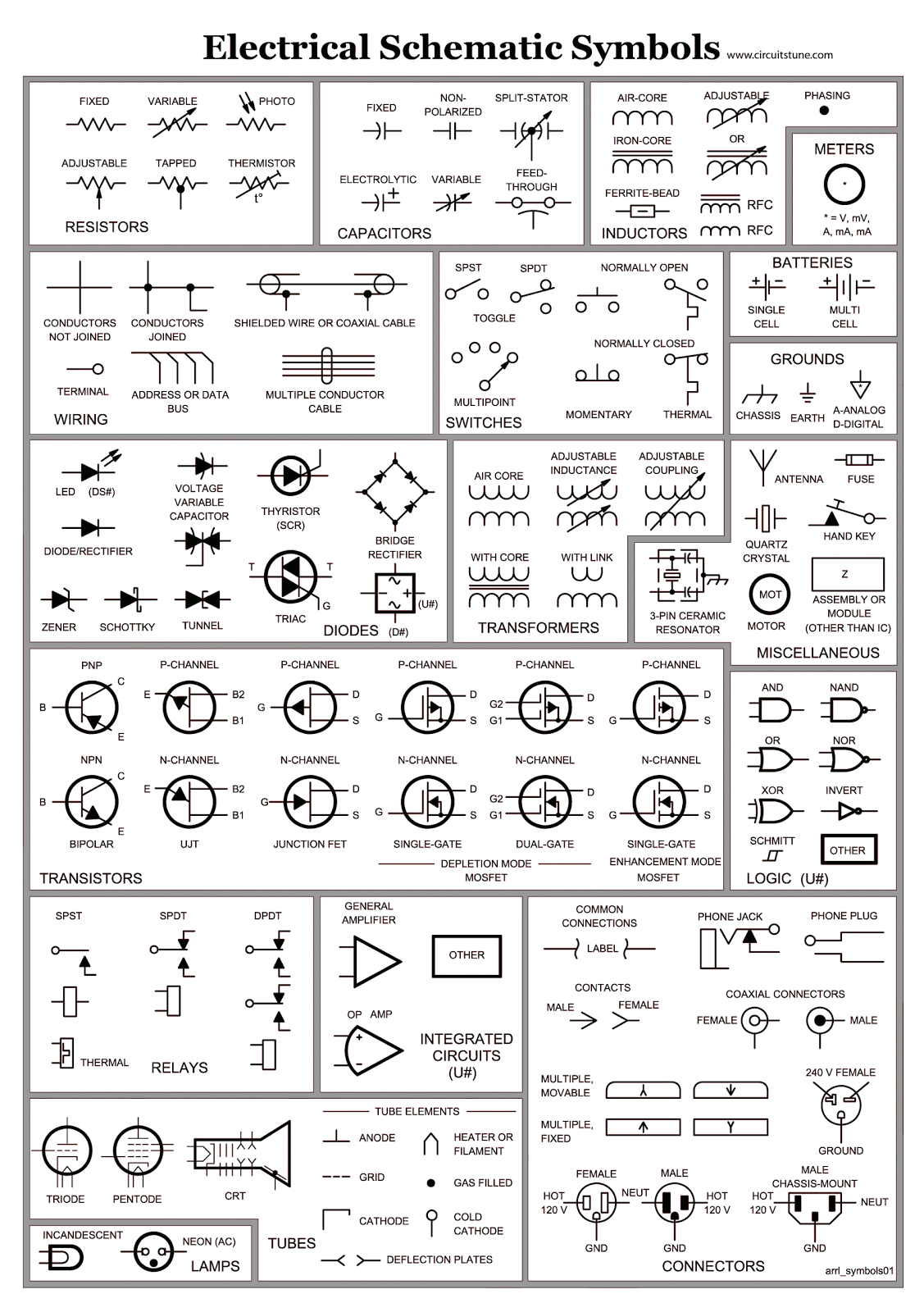
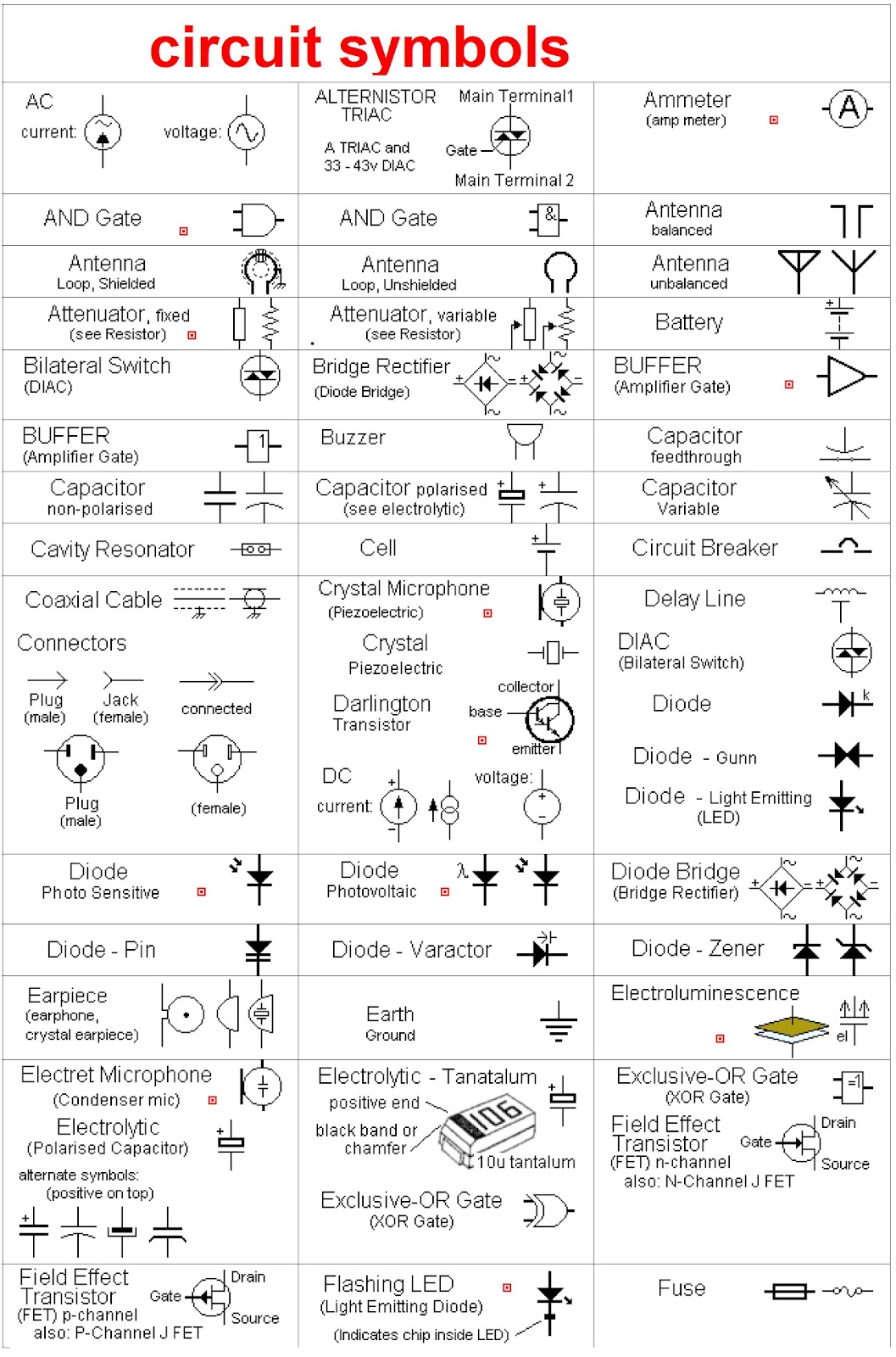
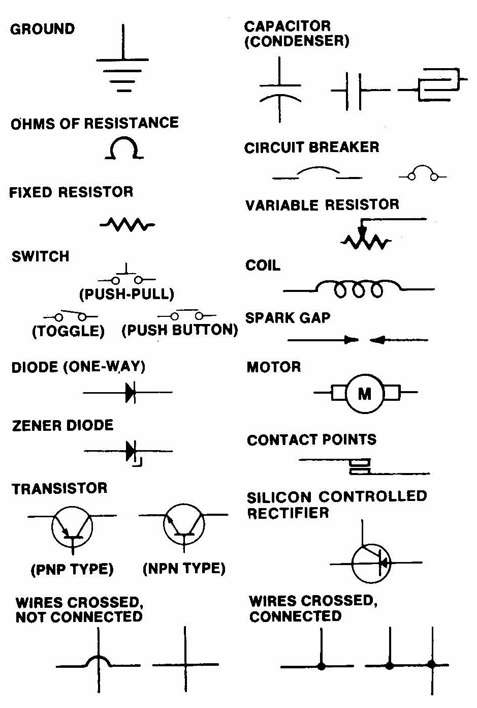
Resistors are represented by a zigzag line. Capacitors typically use two parallel lines. A battery is symbolized by a combination of long and short parallel lines. Transistors have more complex symbols reflecting their three terminals. Integrated circuits are usually represented by rectangles with multiple connection points.
Benefits of using standard symbols include clear communication, efficient troubleshooting, and simplified design processes. For example, a standard resistor symbol allows any engineer to quickly identify the component and its value on a schematic, regardless of their native language.
Advantages and Disadvantages of Standardized Electrical Schematic Symbols
| Advantages | Disadvantages |
|---|---|
| Universal understanding | Initial learning curve |
| Simplified design process | Potential for confusion with similar symbols |
| Efficient troubleshooting | Requires ongoing updates and standardization |
Best practices include using clear and consistent symbols, labeling all components, and ensuring the schematic is well-organized. For example, always use the correct symbol for a diode, ensuring it points in the direction of current flow.
A real-world example is a simple circuit diagram for a flashlight, which typically includes symbols for a battery, switch, and light bulb.
A common challenge is misinterpreting similar symbols, such as a diode and a Zener diode. The solution is to carefully review the symbol definitions and ensure correct usage.
FAQ: What is the symbol for a ground connection? Answer: The ground symbol is typically represented by three horizontal lines decreasing in length.
A helpful tip is to practice drawing and interpreting schematics regularly to solidify your understanding of the symbols.
In conclusion, understanding electrical schematic symbols is essential for anyone working with electrical circuits. From designing complex systems to troubleshooting simple appliances, the ability to interpret these symbols allows for clear communication and safe practices. By learning the history, meanings, and best practices for utilizing these symbols, you empower yourself to effectively navigate the world of electronics. Mastering these symbolic representations not only unlocks the intricate workings of electrical circuits but also opens doors to innovation and problem-solving in the field of electrical engineering. Embrace the learning process and continue exploring the fascinating world of electrical schematic symbols – the key to unlocking the power of electrical design.

Electrical Symbols in PDF for Free Download | YonathAn-Avis Hai

Electrical Wire Schematic Symbol | YonathAn-Avis Hai

Refrigeration Symbols For Schematics | YonathAn-Avis Hai

Electrical Schematic Diagram Symbols | YonathAn-Avis Hai

List Of Electrical Schematic Symbols | YonathAn-Avis Hai

Electrical Circuit Schematic Symbols | YonathAn-Avis Hai

Basic Electronic Schematic Symbols | YonathAn-Avis Hai

Electrical Circuit Diagram Symbols List | YonathAn-Avis Hai

symbols on an electrical schematic | YonathAn-Avis Hai

Symbols On An Electrical Schematic | YonathAn-Avis Hai

symbols on an electrical schematic | YonathAn-Avis Hai

symbols on an electrical schematic | YonathAn-Avis Hai

symbols on an electrical schematic | YonathAn-Avis Hai

Electrical Schematic Symbols Chart Pdf | YonathAn-Avis Hai