Mastering Electric Motor Control: Schematics Decoded
Ever wondered how machines seamlessly whir to life and execute precise movements? The secret lies within the intricate world of electrical motor control circuits, visually represented by electrical motor control schematics. These diagrams are the blueprints that dictate how electrical energy is channeled to control motor operation, impacting everything from industrial automation to household appliances.
Understanding these visual representations is crucial for anyone working with electric motors. Whether you're a seasoned engineer or a curious enthusiast, deciphering these diagrams unlocks the ability to troubleshoot, maintain, and even design motor control systems. Think of them as the language spoken between engineers and the machines they command.
From basic start-stop mechanisms to complex variable speed drives, the world of motor control is vast and ever-evolving. This complexity is reflected in the diagrams themselves, which can appear daunting at first glance. But fear not, with a systematic approach, you can unravel these schematics and harness the power they hold.
Electrical motor control diagrams have a rich history, evolving alongside advancements in electrical engineering. Early diagrams were simple, reflecting the rudimentary nature of motor control technology. As technology progressed, these diagrams became more complex, incorporating elements like relays, contactors, and programmable logic controllers (PLCs). This evolution reflects the increasing sophistication of motor control, enabling precise control, automation, and energy efficiency.
The importance of these diagrams cannot be overstated. They are essential for troubleshooting malfunctions, performing maintenance, and ensuring the safe and efficient operation of motor-driven systems. Imagine a factory assembly line grinding to a halt because of a faulty motor. The control diagram acts as a roadmap, guiding technicians to pinpoint the source of the problem and quickly restore functionality. This translates to minimized downtime and increased productivity.
A simplified example of a motor control schematic would be a basic start-stop circuit. This circuit usually includes a power source, a motor starter (often a contactor), and a stop button. The diagram visually depicts the wiring connections between these components, showing how the motor is energized and de-energized. More complex diagrams incorporate elements like overload protection, reversing controls, and variable frequency drives (VFDs).
One key benefit of understanding motor control diagrams is improved troubleshooting. By tracing the circuit through the diagram, technicians can identify the root cause of malfunctions more efficiently. Another advantage is enhanced system design. Engineers use these diagrams to design new motor control systems, optimizing performance, safety, and efficiency. Furthermore, clear diagrams facilitate effective communication between engineers, technicians, and operators, ensuring everyone is on the same page regarding system operation and maintenance.
Advantages and Disadvantages of Using Electrical Motor Control Diagrams
| Advantages | Disadvantages |
|---|---|
| Facilitates troubleshooting | Can be complex and require specialized knowledge |
| Enables efficient system design | May become outdated if system modifications are not reflected in the diagram |
| Improves communication and collaboration | Different standards and symbols can create confusion |
Best practices for implementing electrical motor control schematics include using clear and standardized symbols, ensuring proper documentation, regularly updating diagrams to reflect system changes, incorporating safety features, and validating the design before implementation.
A real-world example is the control system for a conveyor belt in a manufacturing plant. The diagram would depict the motor, sensors, and control logic required to regulate the speed and direction of the belt. Another example is the control system for an elevator, where the diagram would show how the motor is controlled to move the elevator car between floors.
A common challenge is dealing with outdated or inaccurate diagrams. The solution is to implement a robust system for maintaining and updating diagrams. Another challenge is the complexity of modern control systems. The solution is to adopt modular design principles and use simulation software to test and validate designs.
Frequently asked questions include: What are the common symbols used in motor control diagrams? How do I read a ladder logic diagram? What is the difference between a contactor and a relay? What is a VFD and how does it work? What are the safety considerations for motor control circuits? How do I troubleshoot a motor control circuit using the diagram? What are the different types of motor starters? What are the advantages of using PLCs in motor control?
Tips and tricks for working with electrical motor control diagrams include using specialized software for drawing and simulating circuits, referencing industry standards for symbols and terminology, and seeking guidance from experienced engineers.
In conclusion, electrical motor control diagrams are indispensable tools for anyone working with electric motors. From simple start-stop circuits to complex automation systems, these diagrams provide a visual representation of the control logic, enabling efficient troubleshooting, design, and communication. Understanding and mastering these schematics is key to optimizing motor performance, ensuring safety, and driving innovation in a world increasingly reliant on automated systems. By embracing best practices, staying updated with advancements in motor control technology, and utilizing available resources, you can effectively harness the power of electrical motor control diagrams and contribute to the seamless operation of countless applications. Explore further by researching online resources, consulting specialized textbooks, and connecting with industry professionals to deepen your understanding and expertise in this vital field.

electrical motor control diagram | YonathAn-Avis Hai

Reverse Forward Circuit Diagram Pdf | YonathAn-Avis Hai

Motor Control Schematic Symbols | YonathAn-Avis Hai

Wiring An Electric Circuit | YonathAn-Avis Hai

DIAGRAM Three Phase Motor Control Circuit Diagram | YonathAn-Avis Hai
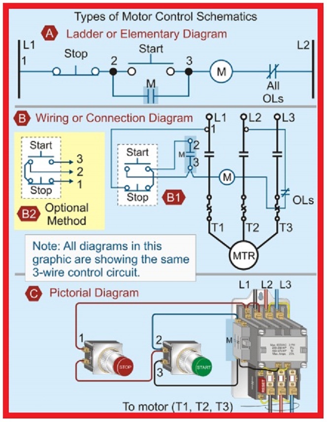
Electrical Motor Control Schematics | YonathAn-Avis Hai
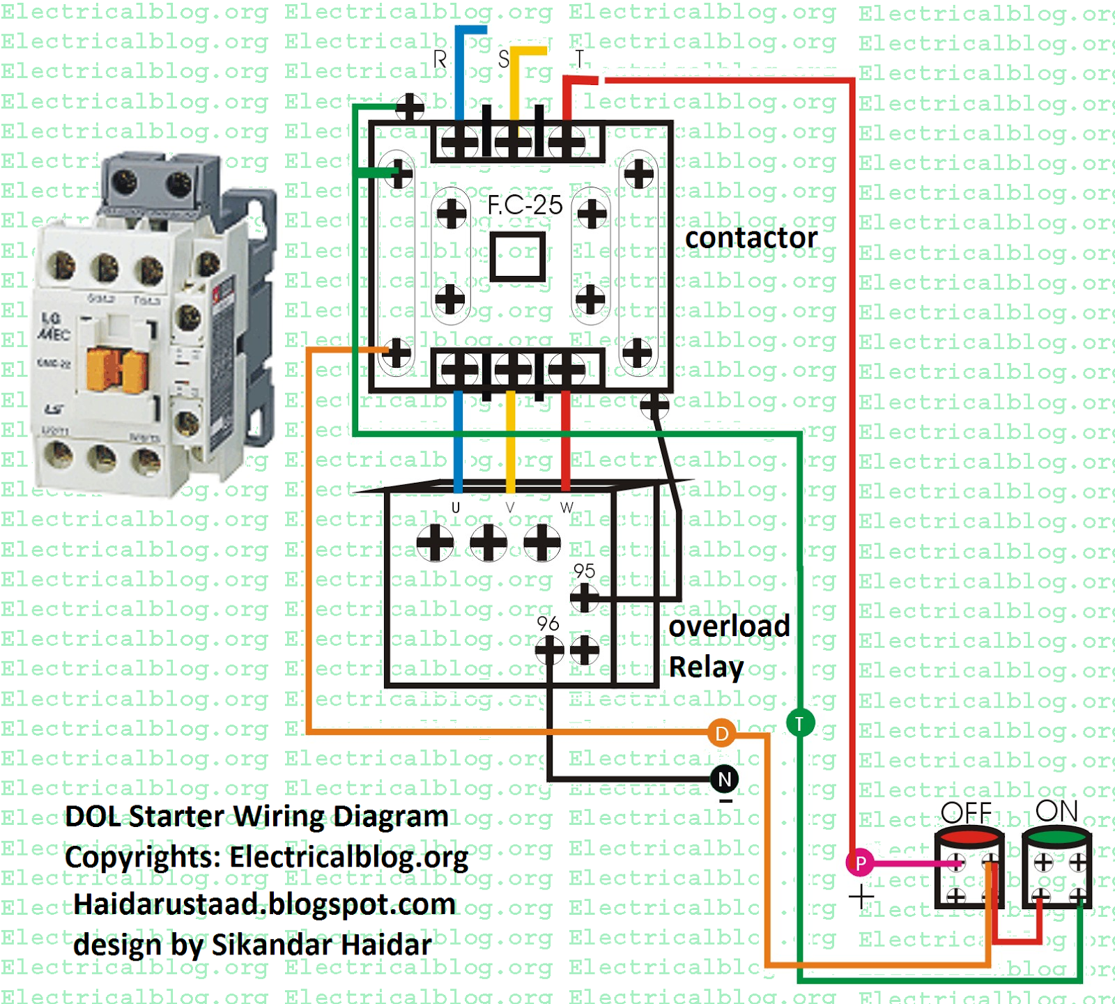
Electrical Wiring Diagrams Motor Starters | YonathAn-Avis Hai

Electric Motor Control Schematic | YonathAn-Avis Hai

Electric Motor Wiring Diagrams Symbols | YonathAn-Avis Hai

Wiring Diagram Of Motor Control | YonathAn-Avis Hai

Wiring Diagrams For Motor Control Circuits | YonathAn-Avis Hai

How To Wire A 3 Phase Contactor | YonathAn-Avis Hai
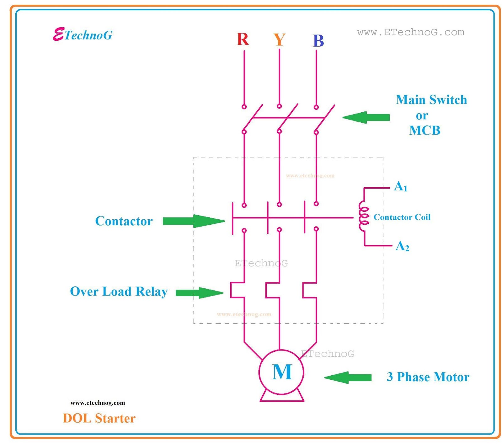
Direct Online StarterDOL Starter Diagram Full Explained | YonathAn-Avis Hai
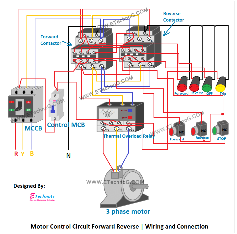
Three Phase Motor Control Circuit Diagram Pdf | YonathAn-Avis Hai
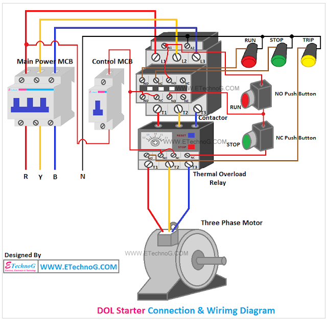
Dol Starter Circuit Diagram Single Phase | YonathAn-Avis Hai