Mastering Electrical & Electronics Symbols: A Comprehensive Guide
Ever looked at a circuit diagram and felt lost in a maze of lines and squiggles? Understanding electrical and electronic symbols is the key to unlocking this world. These symbols are the language of circuits, providing a concise and universally understood way to represent components and their connections. Whether you're a budding hobbyist, an aspiring engineer, or simply curious about electronics, grasping these fundamental symbols is crucial.
Electrical and electronics diagrams are more than just pictures; they're blueprints for how electrical systems function. Imagine trying to build a house without blueprints – chaotic, right? Similarly, these graphical representations, filled with standardized symbols, provide a clear roadmap for designing, building, and troubleshooting electrical circuits. This visual language is essential for effective communication among engineers, technicians, and hobbyists worldwide.
The origins of these symbols can be traced back to the early days of electrical experimentation. As scientists and inventors began working with electricity, they needed a way to document their circuits. Initial representations were often crude drawings, evolving over time into the standardized symbols we use today. Organizations like the International Electrotechnical Commission (IEC) and the Institute of Electrical and Electronics Engineers (IEEE) play a vital role in maintaining and updating these standards, ensuring consistency and clarity across the globe.
A key challenge in the world of electronic symbols is maintaining consistency. With the rapid advancements in technology, new components and functionalities are constantly emerging. This requires ongoing efforts to develop and standardize new symbols that accurately reflect these innovations. Furthermore, different industries and regions may sometimes use variations of standard symbols, highlighting the importance of referencing relevant standards and guidelines.
Understanding electronic diagrams is paramount for anyone working with electrical or electronic systems. From simple household wiring to complex computer circuits, these diagrams provide essential information for design, installation, maintenance, and troubleshooting. Without a solid grasp of the symbols used, interpreting these diagrams becomes nearly impossible, leading to potential errors, malfunctions, and safety risks.
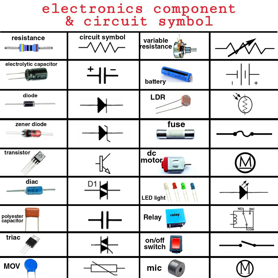
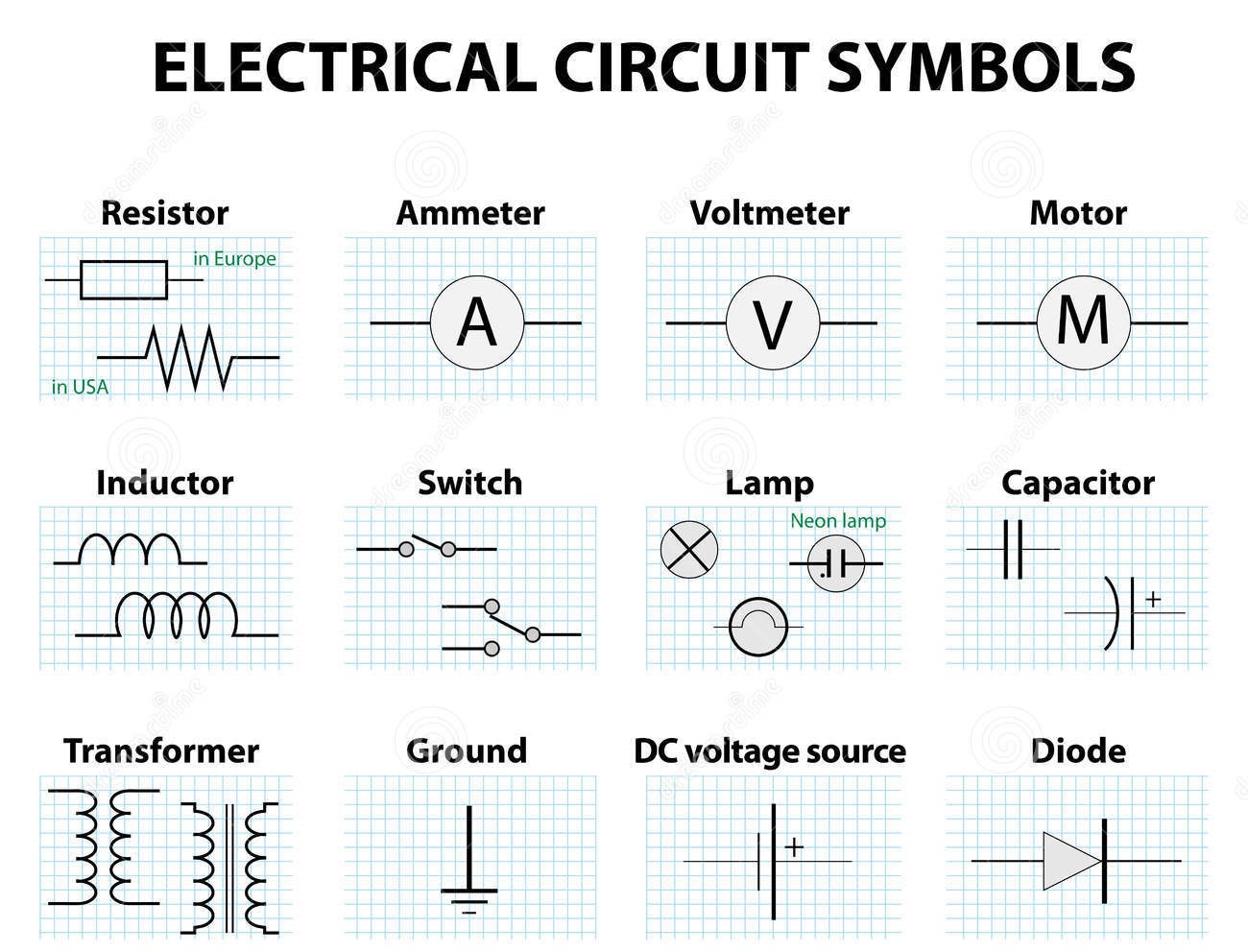
Let's explore some common examples: a resistor, which restricts current flow, is represented by a zigzag line; a capacitor, which stores electrical energy, is symbolized by two parallel lines; a diode, which allows current to flow in only one direction, is shown as an arrow pointing towards a line. These are just a few of the many symbols that form the lexicon of electrical and electronic diagrams.
One major benefit of using standardized symbols is improved communication. These symbols transcend language barriers, allowing engineers and technicians from different countries to easily understand and collaborate on projects. This universal language fosters efficiency and reduces the risk of misinterpretations.
Another significant advantage is enhanced safety. Accurate and clear diagrams, based on standard symbols, are essential for safe installation and maintenance of electrical systems. Misinterpretations of symbols can lead to dangerous wiring errors, potentially causing shocks, fires, or equipment damage.
Finally, standardized symbols facilitate troubleshooting. When a circuit malfunctions, a technician can use the diagram to identify the faulty component quickly. This saves valuable time and resources, enabling faster repairs and minimizing downtime.
Advantages and Disadvantages of Standardized Symbols
| Advantages | Disadvantages |
|---|---|
| Improved communication | Requires learning and memorization |
| Enhanced safety | Potential for variations and misinterpretations |
| Facilitated troubleshooting | Constant evolution with new technology |
A practical action plan for mastering these symbols involves consistent study and practice. Start with basic symbols and gradually expand your knowledge. Utilize online resources, textbooks, and interactive simulations to reinforce your understanding. Practice reading and interpreting simple circuit diagrams, gradually progressing to more complex ones.
In conclusion, understanding basic electrical and electronic symbols is not just a technical skill; it's a fundamental requirement for anyone working with electrical systems. These symbols form the language of circuits, enabling clear communication, promoting safety, and facilitating effective troubleshooting. By investing time and effort in learning and mastering these symbols, you equip yourself with the tools to navigate the world of electronics with confidence and competence. Start your journey today by exploring the numerous online resources and educational materials available, and unlock the power of circuit diagrams. Don't just look at those lines and squiggles – understand them, and open up a world of electrical possibilities.

Symbols For Electrical Schematics | YonathAn-Avis Hai

Basic Electrical And Electronics Symbols | YonathAn-Avis Hai

Electronic Schematic Symbols Pdf | YonathAn-Avis Hai

Electrical Schematic Common Symbols | YonathAn-Avis Hai

Electronics Wiring Diagram Symbols | YonathAn-Avis Hai

Table Of Common Electronics Wiring Symbols | YonathAn-Avis Hai

Schematic Symbols Used In Circuit Diagrams | YonathAn-Avis Hai

Electrical Symbols in PDF for Free Download | YonathAn-Avis Hai

Electrical And Electronic Devices And Symbols | YonathAn-Avis Hai
.jpg)
basic electrical and electronics symbols | YonathAn-Avis Hai

Common Schematic Symbols Used In Circuit Diagrams | YonathAn-Avis Hai

Table Of Common Electronics Wiring Symbols | YonathAn-Avis Hai