Unlocking the Secrets of Hydraulic Schematics
Ever looked at a hydraulic system diagram and felt like you were deciphering ancient hieroglyphs? You’re not alone. Those seemingly simple lines, circles, and squares hold the key to understanding the entire system's functionality. They’re the language of hydraulics, and fluency is essential for anyone working with these powerful systems, from designing and maintaining them to troubleshooting issues.
Hydraulic system schematics, filled with their unique symbols, are far more than just pretty pictures. They're the blueprints that bring these powerful systems to life, allowing engineers and technicians to communicate complex designs and operations efficiently. Without a standardized set of symbols, imagine the chaos! Each manufacturer might develop their own cryptic language, leading to misinterpretations, costly errors, and potentially dangerous situations.
The evolution of hydraulic schematic symbols is a story of increasing standardization and clarity. Early diagrams were often rudimentary, relying on simplified representations that could be ambiguous. As hydraulic technology advanced, so did the need for a more precise and universally understood visual language. This led to the development of standardized symbol libraries, such as those defined by ISO (International Organization for Standardization), ensuring consistent communication across industries and geographical boundaries.
So why are these symbols so important? Think of them as the Rosetta Stone of hydraulics. They provide a common language that transcends spoken language barriers, allowing technicians in Germany to understand a system designed in Japan, or a mechanic in Brazil to troubleshoot a machine built in the United States. This universal understanding is crucial for collaboration, efficient maintenance, and safe operation of hydraulic equipment worldwide.
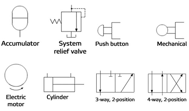
Understanding hydraulic diagrams starts with grasping the meaning of individual symbols. A simple triangle might represent a directional control valve, while a circle with an arrow could denote a rotary actuator. Recognizing these basic elements allows you to break down complex schematics into manageable chunks, tracing the flow of hydraulic fluid and understanding the function of each component within the system.
Hydraulic schematic symbols have a rich history, starting from basic representations and evolving to the standardized symbols we use today. Organizations like ISO have played a vital role in standardization, ensuring a consistent understanding globally.
A key issue related to hydraulic schematic symbols is the need for consistent training and understanding. Misinterpreting a symbol can lead to incorrect diagnoses, improper maintenance procedures, and potential safety hazards. This highlights the importance of comprehensive training programs and readily available reference materials to ensure accurate interpretation of hydraulic schematics.
Three key benefits of understanding hydraulic schematic symbols include: improved troubleshooting, easier design and modification, and enhanced communication between technical personnel.
If you're working with hydraulic systems, mastering the language of schematic symbols is not just recommended – it’s essential. Resources like textbooks, online tutorials, and interactive software can help you build your proficiency. Continuous learning and practical application are key to becoming fluent in this visual language.
Advantages and Disadvantages of Standardized Hydraulic Symbols
| Advantages | Disadvantages |
|---|---|
| Clear Communication | Requires Training |
| International Standardization | Potential for Misinterpretation if not properly trained |
Best practices for implementing hydraulic schematic symbols include using standardized symbols, ensuring clear labeling, maintaining consistent orientation, providing a legend, and keeping the diagram uncluttered.
Real-world examples of hydraulic schematic symbols can be found in diagrams for excavators, aircraft control systems, and industrial machinery.
Challenges in using hydraulic schematic symbols include keeping up with updates to standards, ensuring accurate interpretation across teams, and managing complex diagrams for large systems. Solutions include regular training, utilizing software tools for symbol management, and adopting a modular approach to diagram design.
Frequently Asked Questions:
1. What does a triangle represent in a hydraulic schematic? (Directional control valve)
2. Why are standardized symbols important? (Consistent understanding)
3. Where can I find resources to learn hydraulic symbols? (Textbooks, online tutorials)
4. What is the role of ISO in hydraulic symbols? (Standardization)
5. How can I improve my understanding of hydraulic schematics? (Study and practice)
6. What are the common mistakes in interpreting hydraulic schematics? (Misidentifying symbols)
7. What are the benefits of using software for creating hydraulic diagrams? (Accuracy and efficiency)
8. How can I avoid misinterpreting hydraulic schematic symbols? (Proper training and reference materials)
Tips and tricks for working with hydraulic schematic symbols include using software with built-in symbol libraries, referring to standardized documentation, and practicing with simple diagrams before tackling complex systems. Regularly reviewing and updating your knowledge is also crucial to stay current with the latest standards and best practices.
In conclusion, hydraulic system schematic symbols are the essential building blocks for understanding, designing, maintaining, and troubleshooting hydraulic systems. Their standardized nature allows for a universal language that facilitates clear communication and collaboration amongst engineers and technicians worldwide. Mastering these symbols empowers individuals to confidently navigate the complexities of hydraulic systems, leading to increased efficiency, improved safety, and better overall performance. The importance of accurate interpretation cannot be overstated, as misinterpretations can lead to costly errors and potential hazards. By investing in training, utilizing available resources, and adopting best practices, you can unlock the full potential of hydraulic schematic symbols and ensure the seamless operation of these powerful systems. Take the time to delve into this critical aspect of hydraulics and witness the positive impact it has on your work.

Hydraulic Schematic Symbols Quiz | YonathAn-Avis Hai

Graphical Symbols For Hydraulic Circuits | YonathAn-Avis Hai

Hydraulic Schematic Symbols Explained | YonathAn-Avis Hai

Hydraulic Circuit Schematic Symbols | YonathAn-Avis Hai

Graphical Symbols For Hydraulic Circuits | YonathAn-Avis Hai

Hydraulic System Schematic Symbols | YonathAn-Avis Hai

hydraulic system schematic symbols | YonathAn-Avis Hai

Symbols Of Hydraulic System | YonathAn-Avis Hai

Typical Hydraulic System Diagram | YonathAn-Avis Hai

Symbols Of Hydraulic System | YonathAn-Avis Hai

Water System Schematic Symbols | YonathAn-Avis Hai

Hydraulic And Pneumatic Schematic Symbols | YonathAn-Avis Hai

Symbols For Hydraulic Schematics | YonathAn-Avis Hai

Hydraulic System Schematic Symbols | YonathAn-Avis Hai

How Hydraulics Work Diagram | YonathAn-Avis Hai